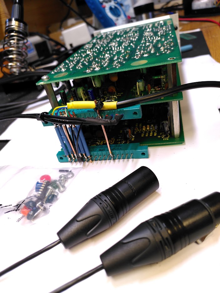
The DBX 906 Flanger was not functional when I received it. The signal went through in bypass but the effect was not working at all, it made some weird oscillating noises. The electrolytic capacitors appear to have been replaced. Repairing this machine can get quite complicated because there is not no technical documentation describing functionality and calibration procedures, except for the schematics. First I made a test jig with two card edge connectors and a double regulated power supply. I found schematics of the power supply section of the DBX 900A mainframe, which I partly used to build the power supply.
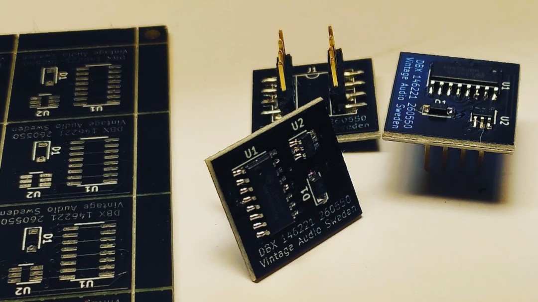
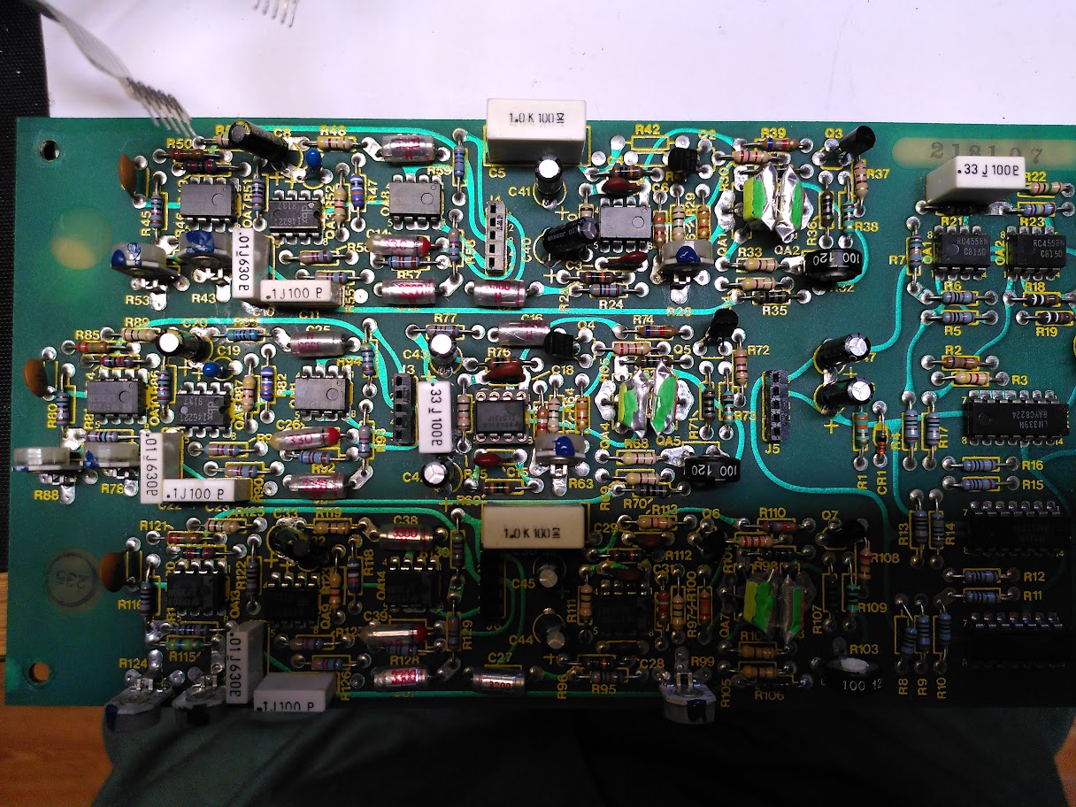
After visual inspection I found out that IC6 (4069 CMOS hex inverter) was burned. Replacing the part did not solve the problem. I found out that there is a problem on the compander card, which contains one compressor and two expanders. The compressing part on the card seems to be not working. The circuit of this feedback compressor is quite complicated to understand and with the limited schematic not easy to debug. Spending time measuring around on the compander card made it clear that at least one of the proprietary DBX IC’s used in the precisive rectifying of the audio signal was defective. These are not available anymore but I was able to reverse engineer the IC and design a small board with a low profile to substitute this IC. This small, low profile board (together with a new socket) actually fits in the tight space in between the compander card and the analog card of the flanger. Why did it brake down? The C20 tantalum 20uF capacitor was shorted. I replaced all three on the card with low ESR electrolytes. (C08, C20, C33) This is a known problem with tantalum capacitors when a constant voltage potential is present over the timespan of years: they short out! The failure probably took down the other active components too. The replacement of the DBX IC and the capacitors were not yet enough to get this section fully working, two of the three dual Opamps were also defective and have been replaced with TL072 substitutes, together with high quality IC sockets. Although a control signal was present now, it was still very unstable and all over樂威壯
the place. I replaced C15 and C18, trying to hopefully solve the high frequency oscillation problem, with no luck. Resoldering all the solder joints on the board and a thorough inspection of all the parts led me to resistor R83 which has been replaced in the past. But, it replaced by a wrong value. Instead of 4R7 it was replaced with a 4k7 resistor!! After replacing this resistor with the original 4R7 value the unite finally came back to life. -sort of- There was still an audible, monotonous, spiking oscillation present in all the active audio circuitry, both on the wet and dry signal. Following the traces I suspected Opamps AO3, AO4 and AO5. I’ve replaced them with TL071/072 substitutes together with high quality sockets, but this did not help solving the oscillation problem. Further investigation led me to IC8 and IC9 , where IC9 (4006 CMOS 8-stage static shift register) measured faulty in my logic tester. IC8 measured still good. But with both IC8 and IC9 out of the circuit (they both involve the noise source of the modulation circuit) the spiking was gone. It turns out that IC8 is faulty too, probably taking too much current and/or injecting spikes on the ±15V power rails. It took a while to get a hold on an original substitute for the long obsolete IC9 (4006 CMOS shift register), while obtaining a NOS replacement for IC9 (4070 CMOS XOR gate) was easy. Now the unit is working again, although in need of proper calibration. After I cleaned the switches S1 and S2 (both were not conducting as they should) I had to come up with a procedure to calibrate the flanger. Since there is no procedure described, lacking a proper service manual, I had to come up with a plan myself following the datasheets of the two different BBD chips. It took some time but the whole unit is calibrated, giving care for details, using the oscilloscope for certain parts and my ears for others. Now the unit works as it should although there is still a bit of oscillation or clocking audible. I changed OA12, OA13 and OA14 for new TL072s but this did not solve the problem. I finally narrowed the source down to the clocking of the random-modulation source. Changing IC8 with a new part made it even worse. I suspect that this is a design flaw. It can probably be solved but that is going to take even more time. Without IC8 the unit has no random-modulation source but works flawless without anything leaking into the audio path.